Adding keyboard connectors to a Schober Recital organ

Home
Cleaning keyboards
Adding connectors
Devtronix generators
PedalboardSpecification

Introduction

It always seemed to me the keyboards should have had connectors so they could be unplugged for cleaning or adjustment.  Faced with a major cleaning, I decided it was time to add the connectors.  Installing the sockets is somewhat time consuming -- about 6 hours -- but I think its worth the trouble.  Much of my procrastination about cleaning the contacts was due to the lack of sockets, and as it turned out I would have had to solder and unsolder each keyboard several times during cleaning and testing.

After some searching, I decided to use 7-pin DIN connectors (see parts list).  These are relatively inexpensive, and do not look out of place in Schober organs because they have been around since the 1970s.  To use Schober generators with both the Great and the Swell would require 26 connectors, but for now I have installed 15.  This lets me use Schober generators for the Great (13 connectors), and the Devtronix generator on the Swell (2 connectors).  If all goes well, I will add 13 more connectors later so I can also use Schober generators for the Swell or at least for the 2 2/3 foot pitch.

Preparation

The number of connectors you need depends on the kind of tone generators you have.  For the original Schober generators, 13 connectors are needed for each keyboard.  The Devtronix generators require only two per keyboard, To use both kinds of generators with a single keyboard (if you want 2 2/3 foot pitch with Devtronix, for example) requires 14 connectors per keyboard.  Since I have a Devtronix generator on the Swell and the original Schober generators on the Great, I have installed a total of 15 connectors for now and will later increase that to 27.

Once you know how many connectors you need, order the parts, which will usually arrive in less than a week.  I haven't listed any part numbers for the hookup wire, since I salvaged multicolored wire from a discarded piece of telephone cable.  Only about three feet of each color will be needed, but it's important to avoid confusion by using the same colors as the original Schober wiring.

Also make sure you have all the tools required.  While you wait for parts to arrive, you can remove the keyboards by unsoldering all the wires then carefully store them in a safe place.  Be sure always to handle them by holding on to part of the steel frame or the steel shanks of the keys so as not to damage the gold spring contacts.  I usually place both hands near the center of the keyboard, one supporting beneath the fronts of the keys and the other holding on to the backs of the keys near the steel return springs.

Installing the sockets

Removing solder points

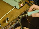
I chose to remove the original solder points before installing the 7-pin DIN sockets.  If you decide to do this, heat each one until it is smoking hot, then immediately remove it with pliers.  They should come out with practically no resistance; otherwise there is a possibility of damaging the printed circuit board.  It's easier to just leave them in place, but I think the job looks tidier if they are removed.


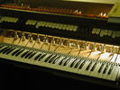
If you click the photograph at left to see the larger version, you will notice pairs of pre-drilled holes for connectors at locations H, J, and K.  I made a cardboard template to locate these accurately, then pushed an awl through the holes in the template to mark where I needed to drill.  Before drilling, remove the stop filter cards if they will be in the way.

When drilling the holes, use a 3/32" bit and be very careful to keep the drill exactly vertical.  If in doubt, its better not to err in the direction that causes the bit to break through the wood behind the terminal boards.  If any holes break through or turn out to be in the wrong place, plug them with round wooden toothpicks then drill again. 


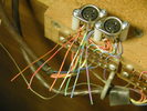
Pre-wired socket
I mounted the sockets with the ground tabs facing the back of the organ, so I decided to wire each socket in counterclockwise order as seen from the bottom.  Going counterclockwise from the ground tab, the sequence is brown, red, orange, yellow, green, blue, violet.


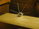
Pre-wired DIN connectors To save time and wire, I made a template showing how long to cut each color of wire for the left and right DIN connector locations.  First cut a thin piece of cardboard to about 3 1/4" (85 mm) square.  Cut two pieces of each color wire to the same length as the template, strip them about 5/16 inch (7 mm), then solder the wires to two DIN sockets in the color sequence described above. 

Mount one of the two sockets on the right pair of holes (as seen from the back of the organ) above a terminal board.  Route the wires to the terminal board, cut them to length (but save the cut off ends!) and strip about 5/16 inch (7 mm) then solder them to the top row of terminals in the left to right sequence brown, red, orange, yellow, green, blue, violet.  Set aside the cut off ends in a safe place, then install the second socket on the left side in the same way and save the cut off wire ends from this socket in a separate place.  (If you forget which is which, the cut off end for the brown wire will be longer on the left socket.)

Note: In the picture, I show two sockets mounted at location W, but locations W and V only need one socket each unless you are using or planning to use Devtronix tone generators.  If you are using Schober generators for both keyboards, mount pairs of sockets at locations U through H.


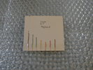
Wire length template
Tape the cut off ends of the wires from the right socket to the piece of cardboard so that one end of each wire is even with the edge of the cardboard.  Label this side of the template Right and GT or Great.  In the same way, tape the cut off wire ends from the left socket to the reverse side of the cardboard, and label this side Left and SW or Swell. (Never mind that the cardboard depicted at left is labeled incorrectly -- my mistake!)


Pre-wired connector
Now pre-wire and install all the right (Great) sockets, connecting them to the top row of terminals in the left to right sequence brown, red, orange, yellow, green, blue, violet.  To make this less tedious, you can pre-wire three to five sockets, then install them before pre-wiring more.  I did about three per evening, so it took about four evenings.


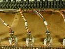
Din plugs installed.
Once all the Great sockets are in place, it's a good time to temporarily re-install the Great keyboard and solder on the DIN plugs.  Because the the wires from the keyboard have to make a fairly sharp turn as they leave the connectors, I removed the rubber sleeves from the connector shell.  To solder each connector, disassemble it and slip the shell over a wire bundle coming from the keyboard.  Set the screw aside in a safe place -- small metric screws are hard to obtain!  Carefully remove the small metal piece from the connector pin assembly, and temporarily plug the pin assembly into one of the DIN sockets.  Now arrange the bundle so that looking at the ends of the wires, the wires are in the same sequence counter clockwise as on the socket (brown, red, orange, yellow, green, blue, violet).  You may need to slip some of the wires out of the last piece of tape on the bundle and re-insert them; possibly the bundle will need to be re-taped. Now cut off the stripped ends of the wires to even out the lengths and strip approximately 1/16" (2 mm) of insulation from each one.  Beginning with the brown wire, solder the wires to the pin assembly.  Note that as seen from the top, the color sequence will appear clockwise rather than counter clockwise.  Check the location of the brown wire on the socket to make sure!

When all the pins are soldered, carefully re-install the small metal piece on the pin assembly, then slip the assembly into the connector shell and re-install the screw.


Temporary installation of keyboard
At this point, you may want to begin cleaning the keyboard contacts, if you have not already done so.  During cleaning, either keyboard can be connected temporarily to the Great DIN sockets for testing.

Wiring the sockets for the Swell is the same as the Great, except the the sockets are mounted on the left at each circuit board location and the wires are soldered to the middle row of holes on the circuit board.


Special instructions if using Devtronix tone generators

If you are using Devtronix tone generators, the pairs of 7-pin DIN connectors at V and/or W need to be wired in a special way.  This will not prevent connecting Schober tone generators if desired.  Mark the right hand socket (as seen from the back of the organ) at V and W with KB for keyboard and the left one DT for Devtronix tone generator.  You will notice that the bottom left hole of the circuit boards at V and W are connected to a bare ground wire.  Remove this wire from both circuit boards, leaving the hole empty.  Now the brown wire on the DIN socket connects between the two sockets, but is not connected to anything else.  Solder the bare ground wire to the ground tab on the KB sockets.  If necessary, you can enlarge the hole in the tab using a pointed tool or a small drill.  Solder the ground tab on each DT socket to a piece of black hookup wire, and then solder the other end of the hookup wire to the braid of the six wire cable that goes from U or V to the stop assembly.  This ground will be used for audio, but the bare wire ground is only to ground the frames of the keyboards.

When installing the DIN plugs on the keyboard (KB) cables for U and V, connect the brown wire from the keyboard (frame ground) to the shell of the connector (solder it to the small metal piece which holds the shell and the pin assembly together). 

If using the Schober generators, connect the red, orange, yellow, green, blue, and violet wires from the keyboard to their usual pins on the connectors (as described above for othe other 7-pin connectors).

If using a Devtronix generator, locate the wire which supplies keying voltage for the Devtronix generators (usually this will be the blue wire attached to the original 16-foot keyboard bus), and solder it to the pin where the brown wire would normally go.  Solder the orange wire in its normal location to provide 2 2/3 foot pitch and the violet wire to its normal location to provide high C.  If you intend to use the Devtronix generator to provide the 16, 8, 4, and 2 foot pitches, do not connect any of the other keyboard busses to the KB connector.

Wire a second DIN plug to the Devtronix generator.  Connect a black wire from the connector shell to ground on the generator, the brown wire to the +15 volt terminal, red to 2 foot pitch, yellow to 4 foot, green to 8 foot, and blue to 16 foot.  Connect another pair of ground and +15 volt wires to pins 1 and 2 respectively on a 3-pin DIN plug, and wire a 3-pin socket to the supply that powers the Devtronix generator.  This allows the generator to be installed and removed together with the keyboard.


Parts List for connectors

The following parts are available from Mouser Electronics except as noted.  See the textto determine the number of connectors you need; the quantities given are the maximum for using both Schober and Devtronix generators on both keyboards.  The Neutrik DIN plugs listed have metal shells, but you can also use less expensive plugs with plastic shells.

Qty
Part number
Description
Comment
28
568-NYS323
7-pin DIN plug
For Swell and Great keyboards, Schober plus Devtronix generators
28
568-NYS326
7-pin DIN socket
For Swell and Great keyboards, Schober plus Devtronix generators
4
568-NYS321
3-pin DIN plug
To connect Devtronix generators & reverb to power supply
4
568-NYS324 3-pin DIN socket
To connect Devtronix generators & reverb to power supply
64
561-K6.875 Nylon spacers #5 x 0.875
Two per DIN connector (I bought 100 for a price break)
56
N/A
#6 by 1.25" sheet metal screw
Obtain from local hardware store (it's probably cheapest to buy a box of 100)


#22 or #24 solid hookup wire
Colors needed: brown, red, orange, yellow, green, blue, violet

Tools

Just like the original construction of a Schober organ, adding the keyboard connectors is labor intensive.  It's worth investing in the right tools if you don't already have them.  In particular, make sure you have a good wire stripper (such as Ideal 45-121, available from Stanley Supply & Services) and a good soldering iron.  A 3/32" drill bit is needed to drill pilot holes for the #6 screws.  An analog or digital volt-ohm meter may come in handy but is not absolutely required.

Last updated May 8, 2007